

Hi guys,
I tried to find a dedicated thread about zerk installation on Miata arms, my search was unsuccessful. -If you know of a dedicated thread just drop the link here.
If you already had a look, you probably found Emilio's page.
I was not so happy about the location of zerks on rear arms.
The lower are, in my opinion, too exposed to be safe.
![Image]()
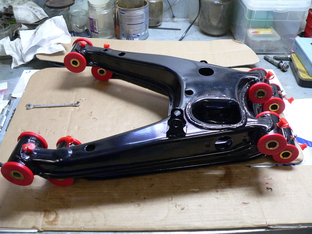
The rear upper arms are known to be a problem because of suspension travel.
![Image]()
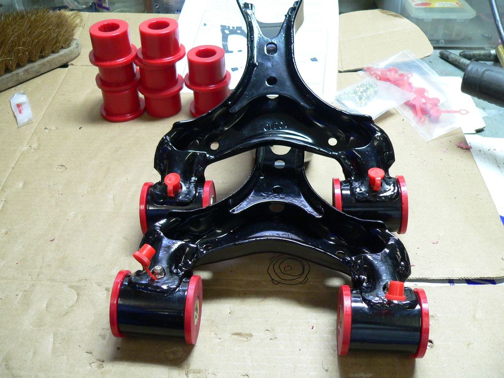
For both rear arms, I have come out with my solution.
Here it goes :
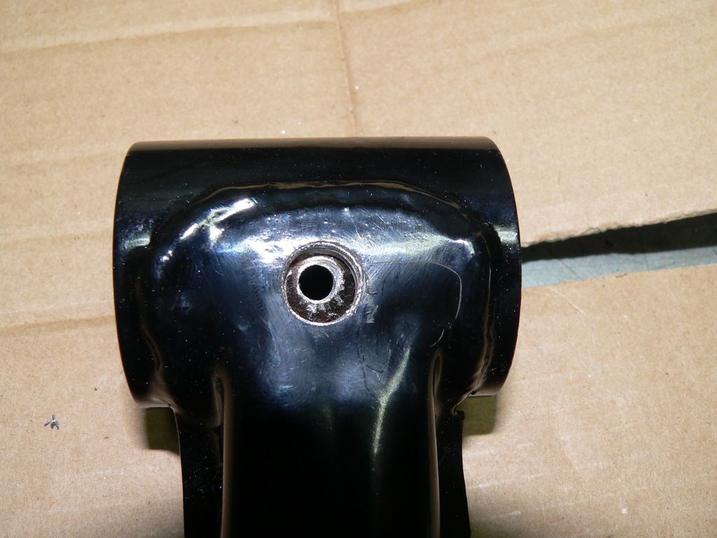
I chose to use an already existing cavity, probably used in plant to hold various sheet metal parts before welding.
Here is the top rear arms, on the left hand, you can see the cavities I was referring to.
![Image]()
I chose to put the zerks in these holes.
My zerks come from here : http://cgi.ebay.co.uk/ws/eBayISAPI..../eBayISAPI.dll?ViewItem&item=230557333229&ssPageName=STRK:MEWNX:IT#ht_500wt_922
specs : M6 thread. 7mm hex key.
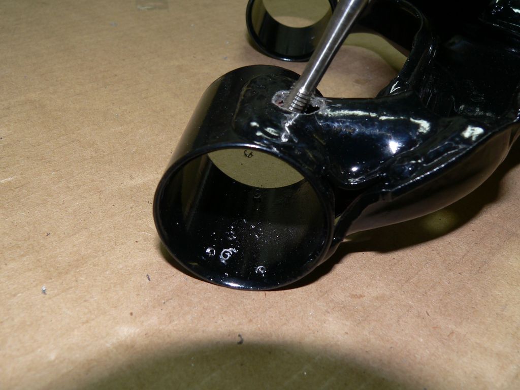
To accommodate their size, I had to enlarge the holes to a good 10mm, 11mm to 12mm are even better but I had no 11 or 12mm drill that day.
Drilled at 10mm + 5mm hole for the zerk, both must be perfectly centered. (the picture makes it look like it's off, but it isn't)
![Image]()
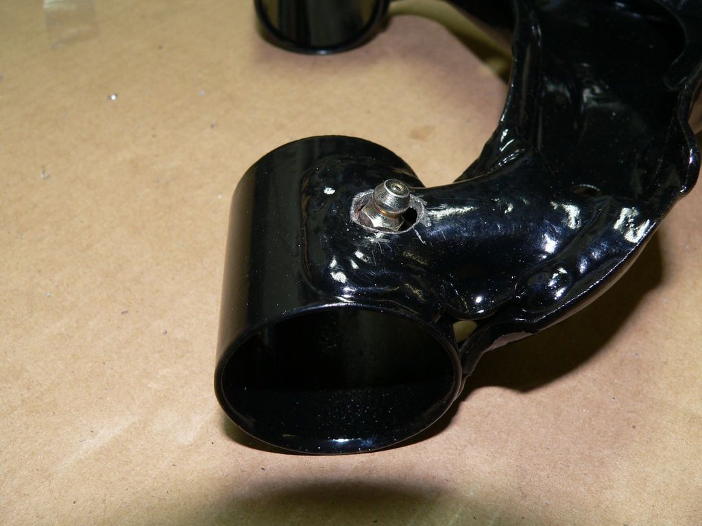
M6 tapping
![Image]()
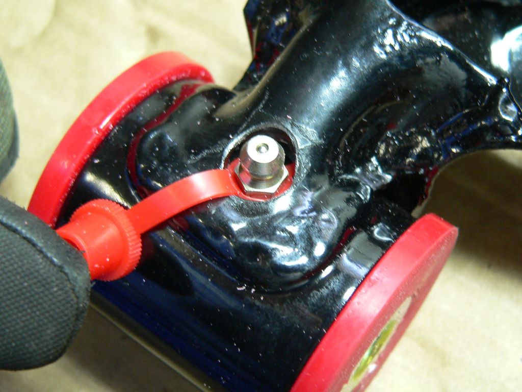
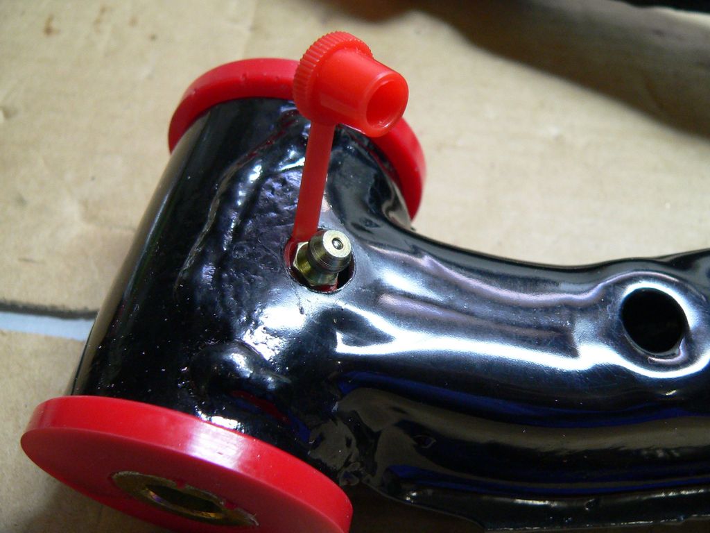
Zerk installed
![Image]()
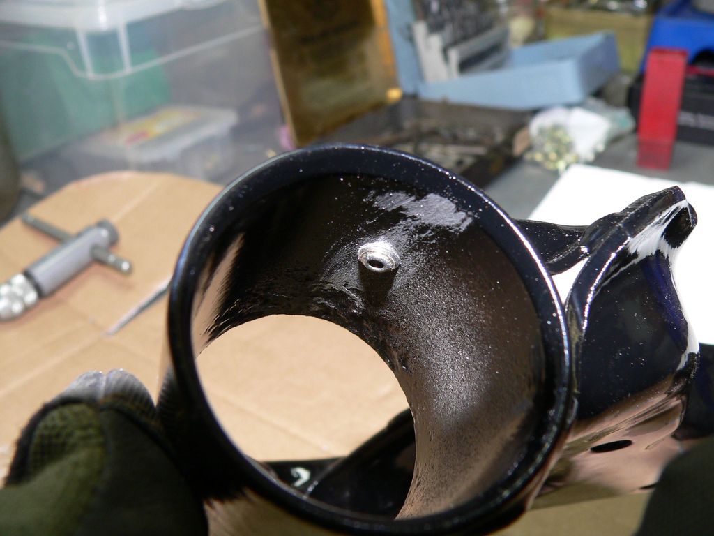
From the inside (of course, deburr as required)
![Image]()
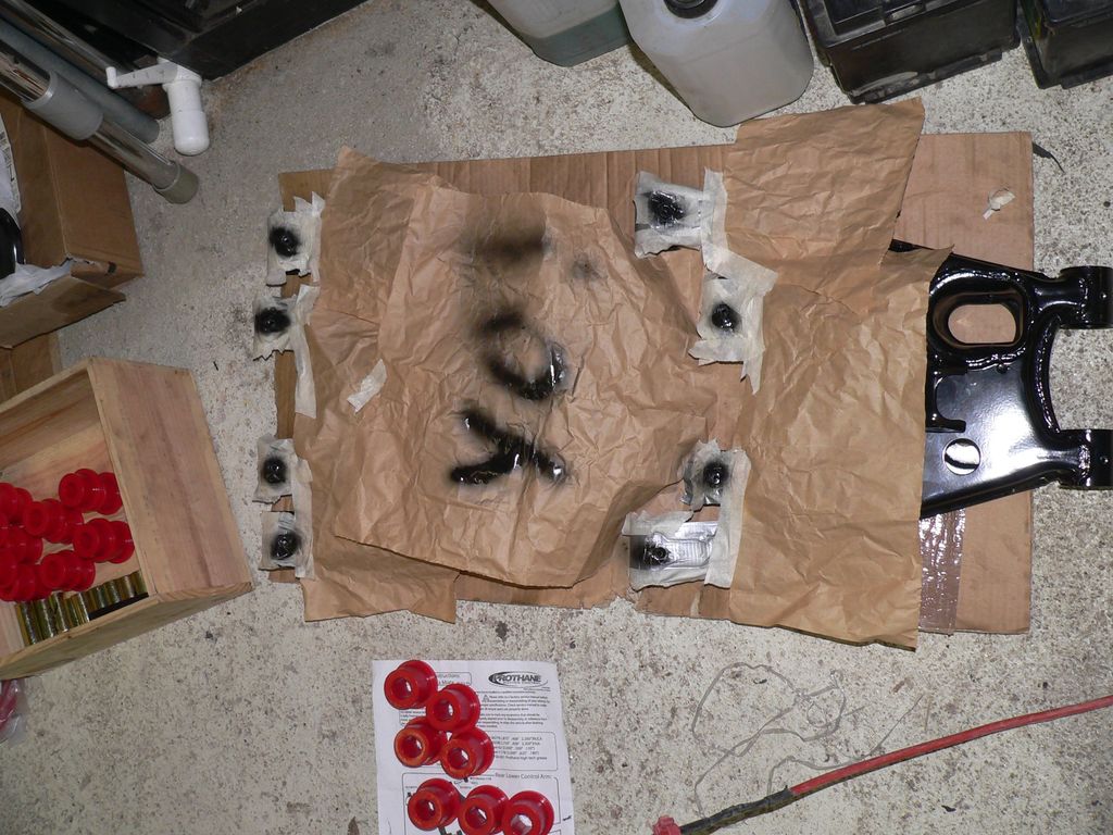
As my arms were powder coated before I had the chance to install the zerks, I removed paint in the process... No problem, a little rattle can and away it goes.
![Image]()
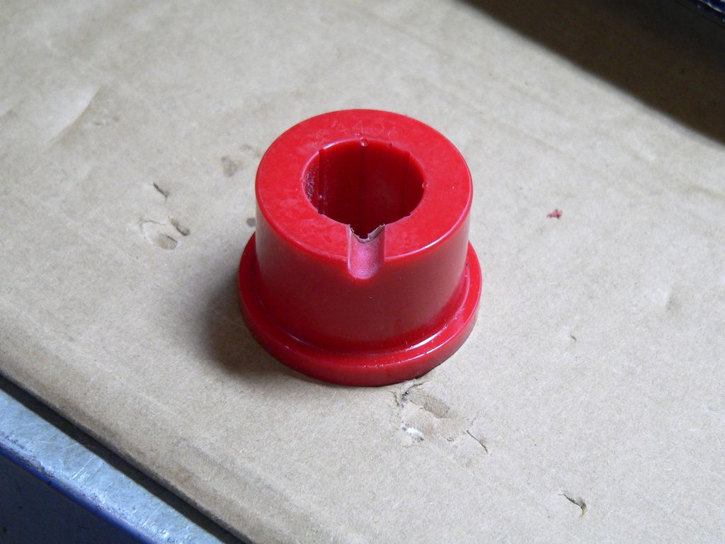
On the bushing side, I slightly modified them to make sure the grease goes through perfectly.
![Image]()
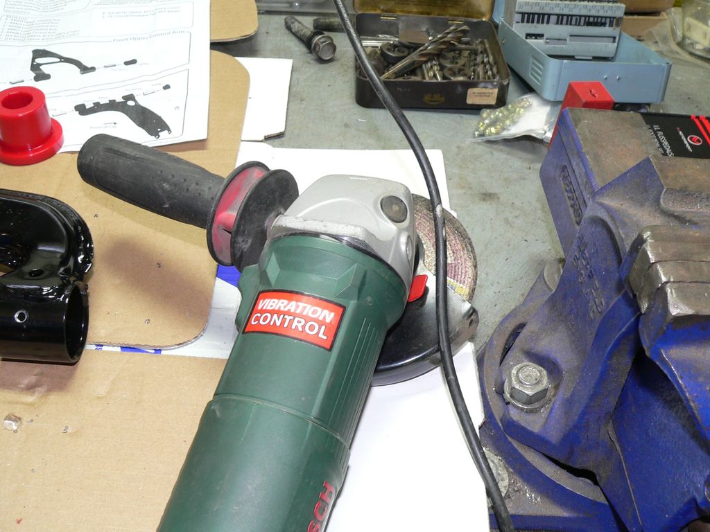
The tool
![Image]()
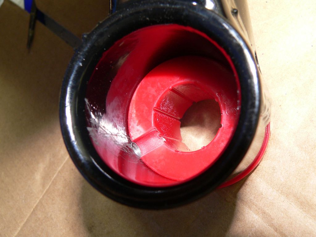
Here is what it looks like once modified & installed
![Image]()
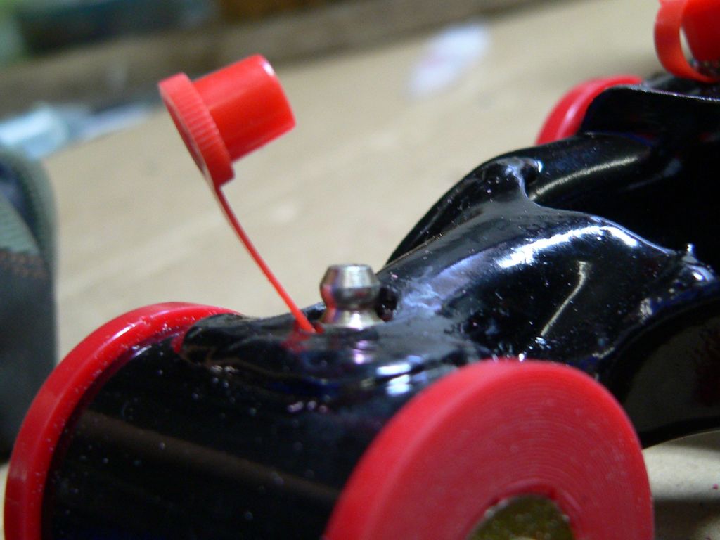
The rear upper arms were done as follows :
![Image]()
With the nipple caps, my 7mm hex key could just fit, this is why I recommend to drill a bit larger than 10mm.
![Image]()
Looking perfect to me !
![Image]()
If you need a scale : look here
Yes, the grease pump still fit on the zerk, just picture it as if it was one of the caps
![Image]()
The rear lower arms were done following the same idea, to avoid any possible damages with objects on the road.
![Image]()
![Image]()
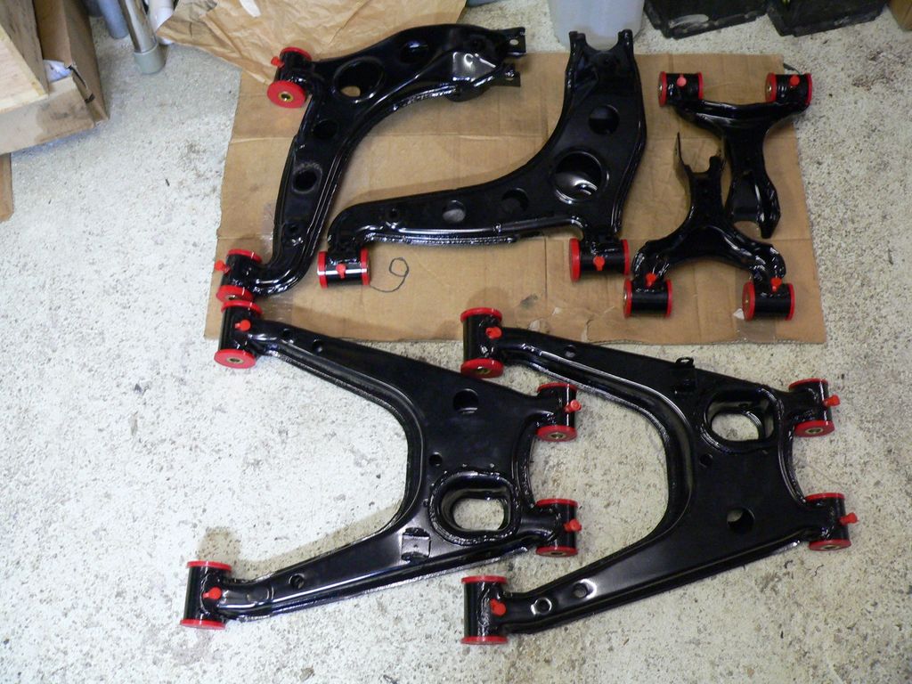
The other locations are pretty straight forward looking at this picture or on 949 website.
![Image]()
One last thing : don't always try to locate the zerk in the center of where it goes, but look at where is the junction between two bushings. It is sometimes offset a few millimeters
Useful links :
zerks on ebay UK
Caps on ebay UK
949 Racing zerk page
My friend's Dustin official "red neck bushing removal tool" thread
Hope it helps!
I tried to find a dedicated thread about zerk installation on Miata arms, my search was unsuccessful. -If you know of a dedicated thread just drop the link here.
If you already had a look, you probably found Emilio's page.
I was not so happy about the location of zerks on rear arms.
The lower are, in my opinion, too exposed to be safe.

The rear upper arms are known to be a problem because of suspension travel.

For both rear arms, I have come out with my solution.
Here it goes :
I chose to use an already existing cavity, probably used in plant to hold various sheet metal parts before welding.
Here is the top rear arms, on the left hand, you can see the cavities I was referring to.

I chose to put the zerks in these holes.
My zerks come from here : http://cgi.ebay.co.uk/ws/eBayISAPI..../eBayISAPI.dll?ViewItem&item=230557333229&ssPageName=STRK:MEWNX:IT#ht_500wt_922
specs : M6 thread. 7mm hex key.
To accommodate their size, I had to enlarge the holes to a good 10mm, 11mm to 12mm are even better but I had no 11 or 12mm drill that day.
Drilled at 10mm + 5mm hole for the zerk, both must be perfectly centered. (the picture makes it look like it's off, but it isn't)
M6 tapping
Zerk installed
From the inside (of course, deburr as required)
As my arms were powder coated before I had the chance to install the zerks, I removed paint in the process... No problem, a little rattle can and away it goes.
On the bushing side, I slightly modified them to make sure the grease goes through perfectly.
The tool
Here is what it looks like once modified & installed
The rear upper arms were done as follows :
With the nipple caps, my 7mm hex key could just fit, this is why I recommend to drill a bit larger than 10mm.
Looking perfect to me !
If you need a scale : look here
Yes, the grease pump still fit on the zerk, just picture it as if it was one of the caps
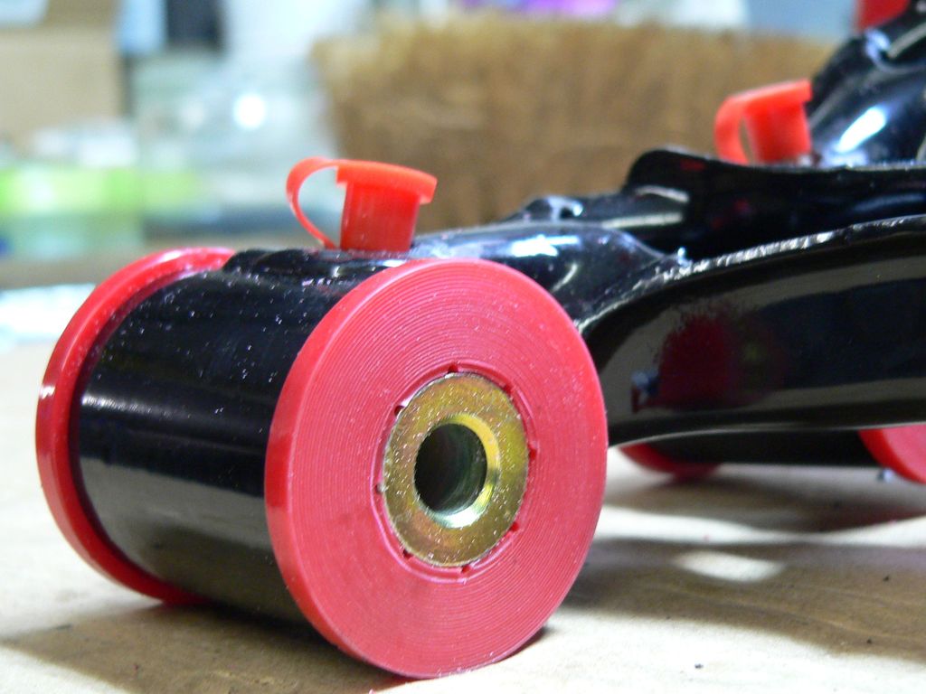
The rear lower arms were done following the same idea, to avoid any possible damages with objects on the road.
The other locations are pretty straight forward looking at this picture or on 949 website.
One last thing : don't always try to locate the zerk in the center of where it goes, but look at where is the junction between two bushings. It is sometimes offset a few millimeters
Useful links :
zerks on ebay UK
Caps on ebay UK
949 Racing zerk page
My friend's Dustin official "red neck bushing removal tool" thread
Hope it helps!


